
How to Efficiently Integrate Hardware into Sheet Metal Part Design?
A Comprehensive Guide to Maximizing Manufacturability, Assembly Speed, and Mechanical Integrity
Hardware integration represents a critical link between standalone sheet metal components and fully realized, structural assemblies. Integrating fastening elements—such as self-clinching nuts, studs, standoffs, and rivets—directly into components enables efficient, secure, and highly repeatable downstream assembly.
A sophisticated hardware strategy yields tangible dividends: accelerated assembly throughput, lower baseline production costs, heightened structural reliability, and simplified in-field maintenance. Conversely, improper selection or poor spatial positioning can trigger a cascade of manufacturing issues, including sheet distortion, installation failures, expensive scrap cycles, and extensive manual rework. This guide outlines structural workflows and strict Design for Manufacturability (DFM) rules required to cleanly embed hardware connections into industrial sheet metal products.
What is Hardware Integration?
Hardware integration is the precise addition of auxiliary components into raw sheet metal parts to enable robust mechanical connections, specialized spacing, or internal mating threads. Instead of relying on tapped threads within thin sheet walls—which lack structural depth and fail under minimal load—or expensive manual welding operations, hardware elements are permanently embedded via localized cold-flow deformation, physical expansion, or mechanical deformation.
The core selection criteria revolve around material properties, operational load profiles, structural accessibility, and lifecycle maintenance profiles. The most common varieties include:
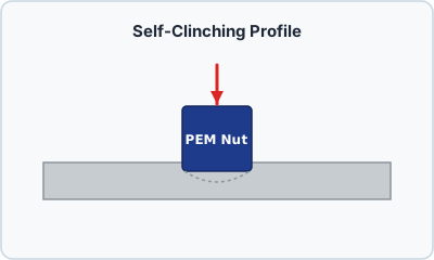
- Self-Clinching Nuts (PEM® Nuts): Displace host material into a specialized retention contour, providing robust, high-torque internal threads.
- Self-Clinching Studs: Project an external thread outward from the sheet panel face to receive external nuts.
- Standoffs: Threaded spacing pillars used to offset parallel substrates, such as PCBs, away from structural chassis walls.
- Rivet Nuts: Blind-installation internally threaded sleeves that physically collapse on the hidden side of an assembly.
- Captive Screws & Blind Rivets: Retained structural hardware that avoids loose components during field servicing.
Pro-Tip: Base Material Hardness Matrix. For self-clinching fasteners to properly set, the host sheet metal must possess a lower Rockwell hardness rating than the hardware itself. If the sheet is too hard, the hardware knurl cannot force the host material to cold-flow into its undercut, causing installation slip or outright push-out failure.
Material Thickness & Geometric Constraints
Every fastener family is limited by physical constraints dictated by the host sheet's gauge thickness. Attempting to install high-performance hardware into a gauge that falls short of manufacturer-recommended minimums is an open invitation to structural compromise.
| Hardware Family / Variant | Standard Thread Code | Minimum Required Host Sheet Thickness | Recommended Punch Hole Diameter (+0.08mm / -0.00) |
|---|---|---|---|
| Self-Clinching Nut | M3 | 1.0 mm | 4.22 mm |
| Self-Clinching Nut | M4 | 1.2 mm | 5.41 mm |
| Self-Clinching Nut | M5 | 1.5 mm | 6.40 mm |
| Heavy-Duty Stud | M6 | 2.0 mm | 8.75 mm |
Risk of Non-Compliance with Minimum Sheet Thickness. Violating the lower bounds of material thickness rules yields three catastrophic failure modes: poor retention force (leading to loose spin-outs under assembly torque), dramatic pull-out failures under tensile loading, and sheet deformation where the surrounding metal buckles or warps out-of-flat during the pressing stroke.
Engineering Placement Formulas (DFM Rules)
1. Clearances Relative to Active Bends
Proper hardware integration requires strict adherence to spatial clearances relative to geometric anomalies like sharp bends, raw material edges, or adjacent tooling operations.
Placing fasteners too close to a progressive or coin bending line causes severe material distortion. As the bending tool strikes the metal, the material in the outer tension zone experiences plastic deformation. If a pre-punched fastener hole sits inside this active deformation window, it stretches into an oval shape, rendering hardware insertion impossible or compromising its structural seat.
Minimum distance from bend line: Dbend ≥ Rbend + 2T, where Rbend is the inside bend radius and T is the sheet material gauge thickness.
Practical validation case study: Consider a structural plate with a thickness (T) of 2.0 mm and a specified punch-tool bend radius (Rbend) of 2.0 mm. Applying the DFM rule: Dbend = 2.0 mm + (2 × 2.0 mm) = 6.0 mm. The absolute minimum distance from the inner profile edge to the edge of the hardware installation hole must be kept at 6.0 mm or wider to guarantee zero localized hole deformation.
2. Edge Distance Margins
If hardware is driven too close to a free edge, the radial forces generated by material displacement will push outward, swelling or tearing the sheet edge. This yields an unsightly profile bulged outward and severely undercuts the hardware's ultimate pull-out and torque ratings.
Minimum edge distance: Dedge ≥ 1.5 × Dhole, where Dhole is the diameter of the pre-punched mounting hole.
Example: For an M5 self-clinching nut requiring a mounting hole diameter of Dhole = 6.4 mm, the minimum edge spacing translates to 1.5 × 6.4 mm = 9.6 mm from the center point of the hole to the outermost cut edge.
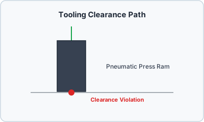
Additionally, designs must accommodate the structural width of installation tooling. If an internal flange is placed too close to a clinch nut location, the industrial press anvil cannot sit flush against the sheet metal panel, forcing secondary operations, expensive custom tooling, or unrepairable cosmetic deformation.
Design for Assembly (DFA) & Optimization Strategies
Effective engineering minimizes part counts and streamlines the layout to facilitate error-free production. Hardware size standardization is highly effective for reducing complexity. Using varied thread types across a single assembly escalates procurement overhead, complicates automated feed tracks, and causes operator placement errors.
Standardization blueprint:
- M3 Family: Dedicated to low-mass internal components, PCBs, and sensitive electronic logic modules.
- M4 Family: The general-purpose baseline for structural partitions, secondary brackets, and outer skins.
- M5 / M6 Family: Reserved for structural frames, high-vibration engine mounts, and primary tie-ins.
Standard Sheet Metal Manufacturing Pipeline
- Profile Generation: Laser cutting, turrets, or CNC punching operations shape the raw flat sheets and pop the mounting holes.
- Hardware Insertion: Hardware elements are automatically or semi-automatically pressed into the flat blank.
- Press Brake Bending: The flat sheets are formed into final three-dimensional geometries.
- Secondary Fabrication: Spot welding or structural arc-welding operations are performed.
- Surface Engineering: Application of powder coats, zinc platings, or conversion coatings.
DFM Engineering Release Checklist
Verify the following checklist points prior to exporting flat patterns and releasing engineering documentation to production:
- Material Substrate Compatibility: Ultimate sheet hardness verified to be lower than the fastener's specified hardness index.
- Minimum Gauge Verification: Base sheet metal thickness satisfies the manufacturer's exact specification limit for the chosen shank size.
- Hole Precision: Nominal pilot hole tolerances strictly matched to the manufacturer's laser/punch tooling chart.
- Bend Interference Clearance: Safe zones evaluated via the Rbend + 2T boundary around all active bend lines.
- Edge Margin Integrity: Distance from any outer profile perimeter to a fastener center point equals or exceeds 1.5 × Dhole.
- Tooling Axis Access: Clearance verified for industrial insertion rams, anvils, and downstream pneumatic torque drivers.
- Fastener Hierarchy Audit: Fastener sizes standardized across the master assembly to eliminate redundant SKU counts.
- Tensile & Torque Budgeting: Calculated pull-out forces and torque resistance meet or exceed the maximum design working stress.
Conclusion
Disciplined, systematic hardware integration separates high-yielding commercial fabrications from trouble-prone designs. By prioritizing manufacturer-recommended parameters and executing rigid DFM geometric checks during initial layout phases, mechanical designers can virtually eliminate downstream manufacturing failures. The resulting products offer streamlined manufacturing profiles, optimized cost structures, and superior field reliability throughout their service lifecycles.